DF05101
De-Link Meter
De-Link Meter BF
1
1
1
1
1
1
11
De-Link Display Operations Manual
This display is a valuable additional meter for providing information to automobile users about engine conditions and other
important factors. When installing and operating this product, be sure to read the cautionary items of this operations manual as
well as those given in the operations manual for the vehicle in which this display will be installed. Obtain a full understanding of
the cautionary items and use the product accordingly.
In this manual, the degree of hazard arising from actions such as improper operation is separated into the 2 levels “Warning” and
“Caution.” In addition, instructions that must be followed for safe and proper use of this product as well as practices that must be
maintained are marked with a “Check” heading. Please read and become familiar with these sections.
In the event that this product (or the vehicle in which it is installed) is lent to or transferred to another person, please be sure this
operations manual accompanies the product.
Before Installation (for installation personnel)
l
Be sure to follow all instructions in this manual to ensure safe installation and operation of the product.
l
Carefully consider the installation location and driver’s operation of the product before installation. Be
sure not to install the unit where it could fall. Improper installation or operation could cause the
product to fall and damage the vehicle or present the severe danger of impeding driving of the vehicle.
l
Do not disassemble or modify this product. Such actions can not only damage or destroy the product
but will also void the warranty.
l
Do not perform installation of this product immediately after the engine has been switched o. The
engine and exhaust system are extremely hot at this time and can cause burns if touched.
l
Ensure that the wiring of this product does not have an adverse impact on the other wiring of the vehicle. The controller or
other electronic components of the vehicle could be damaged.
l
Please keep children and infants away from the installation area. Children may swallow small parts or be injured in other
ways.
Warning
disassemble/
modify
l
This product is designed for use on 12V vehicles. Do not install this product on vehicles with 24V
systems.
l
Do not install the display in a location with much moisture or dust, or where it will be in direct sunlight,
or in an area around heater exhaust vents.
l
Wear gloves to avoid burns when soldering and cuts when working with wiring.
l
When the negative (-) battery terminal is disconnected, equipment such as clocks and audio
components having internal memory may lose their memory data. Follow the operations manual of each component to
reset data after installation of this product.
Caution
24 V
l
After installation is complete, return this operations manual to the customer along with the warranty.
Conrmation
About Installation and Operation
(for customer and installation personnel)
Warning
l
Please have this product installed by the retail store or dealer where it was purchased. Installation by
the customer will void the warranty.
l
Do not disassemble or modify this product. Such actions can not only damage or destroy the product
but will also void the warranty.
l
In order to ensure safe driving, check the information on this display only for short periods of time.
Looking at the display for long periods of time could distract adequate attention from the road and
result in an accident.
l
Discontinue use of this product if nothing is displayed, water gets into the unit, or smoke or a strange odor comes from the
unit. If such a condition occurs, contact the sales outlet or installation personnel as soon as possible. Continued use while
the condition exists could result in an accident or re.
disassemble/
modify
l
The De-Link Display will not operate without connection to De-Link Control Unit II or De-Link Control Unit.
l
When De-Link Meters or De-Link BF Meters are connected, a maximum of 7 components can be connected, including
De-Link Display.
l
See the De-Link System operations manual for installation of De-Link sensors.
l
Only the Speed Mode will be shown on the De-Link Display when no other sensors are connected to De-Link Control
Unit II or De-Link Control Unit. In that case, PEAK Mode and REPLAY Mode will not be available.
l
Be sure the speed signal wire is connected when using this display.
Caution
Main Features (for customer)
l
This product is a multi-purpose monitor for connection to De-Link Control Unit II or De-Link Control Unit. It uses an
organic light emitting diode made by Nippon Seiki.
l
The monitor’s display uses optimal technology for instant readability without afterimages or icker even when seen from
the passenger’s seat or in daylight.
l
Real-time digital information includes speed, oil temperature, water temperature, oil pressure, fuel pressure and exhaust
temperature.
l
Vehicle performance data and peak values are placed in memory for 3 minutes, allowing examination of data after running
the vehicle.
* De-Link Control Unit II has a 3 minute memory. De-Link Control Unit has a 40 second memory.
l
When the RPM signal wire is connected to De-Link Control Unit II or De-Link Control Unit, 2 warning levels can be set in
addition to the warning setting made by Control Unit II or Control Unit, enabling the setting of a total of 3 warning levels.
(Tachometer Triple Warning Mode)
l
When the water temperature sensor is connected, the warm-up condition can be monitored.
l
A graphic animation plays after the ignition is turned on or o. (Opening Mode/Ending Mode)
l
An easily recognizable graphic on each setting screen helps guide easy setting of warnings for De-Link Meters and Step
Graph. (Setting Assistance function)
l
The Warning LED lights when the set warning value is exceeded for oil temperature, water temperature, exhaust
temperature and engine RPM. The Warning LED lights when measured value drops below the set warning value for oil
pressure and fuel pressure.
l
Trouble locations are shown by graphics so that connection problems can be quickly corrected. (Self-Diagnosis function)
l
The structure of the mounting base allows height and angle adjustment so that it can match the shape of the instrument
panel.
l
The De-Link Indicator (sold separately) can be connected to the display.
The following parts are included with this product. Conrm that all parts are present before installing the product. In addition,
these parts are sold separately for part replacement, so contact your retailer for further information.
Parts List (for customer and installation personnel)
Part Name Quantity
Included Parts Set for Meters
(double-sided tape, buer, mounting bracket,
M4 bolt & nut, washer)
Operations Manual
Installation Stay
Set Screw Solderless Connector
Meter Wire (25cm)
Speed Signal Wire (2m)
QuantityPart Name
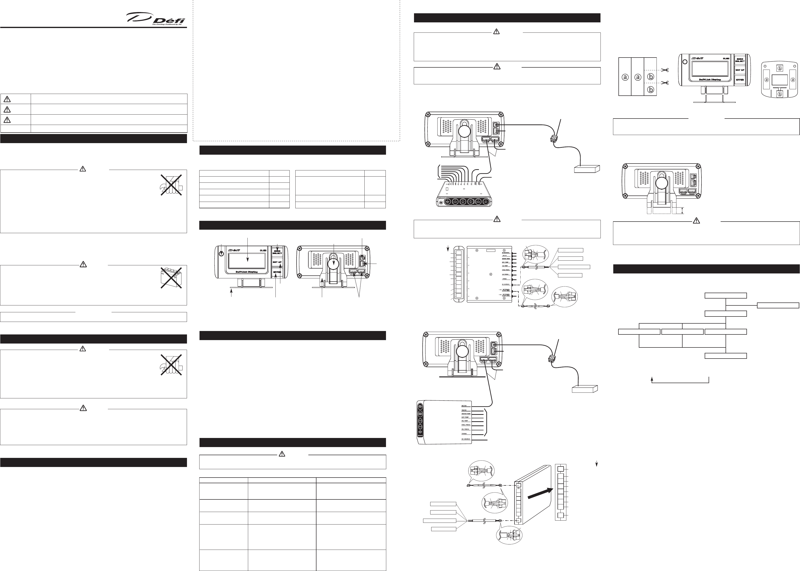
Part Names (for customer and installation personnel)
Warning LED
(Front Side) (Rear Side)
* Organic Light Emitting Diode Display (32 x 80 Full Dot)
Mounting Bracket
MODE SELECT Button
SET UP
Button
Installation Stay
ENTER Button
Set Screw
4 Pin Connectors for Meter Wire
(Doesn't matter which is connected.)
3 Pin Connector for
De-Link Indicator
2 Pin Connector for Speed
Signal Wire
* LICENSED PRODUCT by KODAK
Product Specications (for customer and installation personnel)
l
Power Supply Voltage 8.5 V to 13.5 VDC
(For 12 V vehicles, voltage supplied by De-Link Control Unit II or De-Link Control
Unit.)
l
Current Consumption ILM ON MAX 0.2 A
ILM OFF MAX 0.2 A
l
Operational Temperature Range -20 to +60 C, +14 to +140 F (under 80% relative humidity)
l
Storage Temperature Range -40 to +80 C, -22 to +176 F (under 80% relative humidity)
l
Display Range • Speedometer 0 to 400 km/h, 0 to 240 MPH
• Oil Temperature Meter 50 to 150 C, 122 to 302 F
• Water Temperature Meter 20 to 120 C, 68 to 248 F
• Oil Pressure Meter 0 to 1,000 kPa, 0 to 145 PSI
• Fuel Pressure Meter 0 to 600 kPa, 0 to 87 PSI
• Exhaust Temperature Meter 200 to 1,100 C, 390 to 2,010 F
l
Corresponding Speed Pulse 2, 4, 8, 16, Pulse Free
l
Dimensions (mm) 34 (W) x 103 (D) x 46 (H) (not including mounting base)
l
Gross Weight 290g, 2/3 lb (including display, wires, mounting bracket, packaging)
Control Unit
To De-Link Meter
To De-Link Indicator
To Power Source
To Sensors
The display can be directly connected to either the Control Unit (see gure below) or De-Link Meters.
l
When connected to De-Link Control Unit
Solderless Connector
Speed Signal Wire
Meter
Wires
Speed signal wire of engine
computer unit of the vehicle(ECU)
* When illumination is on, screen brightness will be
reduced by 1 level.
ECU
Control Unit II
Control Unit II
(Rear Side Enlarged Diagram)
M-WARNING
TACHOMETER
WATER TEMP.
EXHAUST TEMP.
OIL TEMP.
FUEL PRESS.
OIL PRESS.
TURBO (BOOST)/
INTAKE MANIFOLD PRESS.
DC SOURCE
METER OUTPUT 1
METER OUTPUT 2
Connector Colors
Power Wire
Meter Wire
Sensor Wire Installation Positions
Red wire - Battery
Orange wire - IGN
(To 12V battery wire)
(To 12V wire when ignition on)
White wire - Illumination
Black wire - GND
(To 12V wire when small lamp on)
(To ground, negative battery terminal)
(white)
(white)
(blue)
(black)
(white)
(blue)
(black)
(white)
(white)
(black)
(white)
l
When installing or working with the display, be sure to follow the applicable instructions for either De-Link Control Unit II
or De-Link Control Unit as shown in their corresponding manuals.
Caution
To De-Link Meter
Meter
Wire
To De-Link Indicator
Solderless Connector
Speed Signal Wire
To Sensors
M-WARNING
To Power
Source
To De-Link Meter BF
Control Unit II
Speed signal wire of engine
computer unit of the vehicle (ECU)
* When connected to Meter Output 1, turning the Illumination
on will reduce screen brightness by 1 level.
When connected to Meter Output 2, screen brightness can be
adjusted independently for daytime by 5 levels and nighttime
by 5 levels.
*
The display can be connected to any of De-Link Control Unit II(see gure below), De-Link Meter and De-Link Meter BF.
Switching the lighting between the daytime mode and nighttime mode is interlocked with the illumination switch of the
vehicle.
ECU
l
When connected to De-Link Control Unit II
l
Be sure to connect the speed signal wire to this product. If the speed signal wire is not connected, the display will stay in
the Special Display Mode.
Caution
l
Carefully read the “Before Installation” and “About Installation and Operation” sections of the manual concerning installation and
operation. Then install the product properly and safely.
l
Installation in an unsuitable location or improper installation can result in the product falling from its position or damage to the vehicle.
* Open terminals are used for inspection of the product, so never connect wiring to these terminals. Connection to these terminals can
damage the product.
Warning
[Wiring Diagram]
Installation (for installation personnel)
l
Installing the Mounting Bracket
1. Cut the supplied double-sided tape. [Figure 1]
2. Insert the protrusions of the mounting bracket into the slots of the meter holder, then secure with the supplied bolt and nut.
[Figure 2]
3. Attach the supplied double-sided tape to the underside of the mounting bracket. Align the mounting bracket with the
location for unit installation, then bend the mounting bracket to the shape of the location while pressing down so the tape
will adhere. To prevent the unit from falling o, secure the mounting bracket with commercially available self-tapping screws.
[Figure 1]
l
Adjusting the height of the installation stay.
Turn the set screw to adjust position on the installation stay so the display is easy to see. (Position can shift up or down by
9.5mm.)
l
Before attaching the mounting bracket to the dashboard, thoroughly clean the mounting surface with a commercial
dashboard cleaner to remove dust, dirt and oils.
Conrmation
[Figure 2] [Figure 3]
l
Be sure to secure the installation stay in place with the set screw.
If the screw is tightened up without the stay being placed between, it can damage the parts and cause failure of the
product.
Caution
l
Illustration of set modes and functions.
[Operational Status Transition Diagram]
Operation (for customer)
SET UP Button
Opening Mode
Set Up Mode
MODE SELECT Button
Warm-Up Mode
Ending Mode
Gauge ModeSpeed ModeTriple Warning Mode
* When water temperature
sensor is connected.
• Warning Settings
• Peak
• Replay
• Warning Settings
• Peak
• Replay
• Warning Settings
• Peak
• Replay
After completion of Opening Mode, Warm-Up Mode elapses and the unit shifts to Triple Warning Mode/Speed Mode/
Gauge Mode. The initial setting is Gauge Mode. Each time the MODE SELECT button is pressed, the mode changes
consecutively to Gauge Mode Þ Speed Mode Þ Triple Warning Mode.
* Triple Warning Mode is not available when connected to De-Link Meter BF.
* Only Speed Mode is available if there are no sensors connected to the De-Link Control Unit II or
De-Link Control Unit. In addition, Peak Mode and Replay Mode will not function.
* Be sure to connect the speed signal wire when using this product.
De-Link Display
Red
Orange
Empty
Black
White
Yellow
Orange
Black
Yellow Black
White
Orange White
Max of 9.5mm up/down
shift possible.
Condition Possible Cause Corrective Action
• Does not display.
• Triple Warning Mode
cannot be set.
• Cannot adjust illumination
of display.
• A line does not light in the
display.
• A button does not operate.
• A dot that should not light
is lighting.
• Speed is not being
recorded.
• Wiring is improper.
• Display is connected to Meter Output 2 of
De-Link Control Unit II.
• Display is connected to Meter Output 1 of
De-Link Control Unit II.
• De-Link Display is damaged.
• The REC button of De-Link Control Unit II
or REC/PLAY button of De-Link Control
Unit has been pressed while the vehicle is
stopped.
• Check wiring as per instructions in De-Link
Control Unit II or De-Link Control Unit
operations manual.
• Connect Display to Meter Output 1 of
De-Link Control Unit II.
• Connect Display to Meter Output 2 of
De-Link Control Unit II.
• Contact the retail outlet where the unit was
purchased.
• This is normal for the product.
Press REC button or REC/PLAY button while
the vehicle is moving.
l
If operation of the product seems unusual, inspect the product to conrm that it is not malfunctioning. If an operational
problem has occurred, it could result in an accident.
* In addition to a general inspection of the product, use the following table to conrm proper operation of the unit.
Warning
Troubleshooting (for customer and installation personnel)
Control Unit
(Rear Side)
Power Wire
Control Unit (Rear Side)
Enlarged Diagram
TACHOMETER
(White)
WATER TEMP.
(Blue)
EXHAUST TEMP.
(Black)
OIL TEMP.
(White)
FUEL PRESS.
(Blue)
OIL PRESS.
(Black)
TURBO (BOOST)/
(White)
INTAKE MANIFOLD PRESS.
Sensor Wire Installation Positions
Meter Wire
(White)
DC SOURCE
(White)
Red wire - Battery
White wire - Illumination
Orange wire - IGN
(To 12V battery wire)
(To 12V wire when ignition on)
Black wire - GND
(To 12V wire when small lamp on)
(To ground, negative battery terminal)
Connector Colors
Meter Wire
Black
Empty
Orange
Red
White
Orange
Yellow
White
Black
OrangeWhite
YellowBlack
Caution
Warning
Confirmation
Danger
indicates an imminently hazardous situation which, if not avoided, will result in death or
serious injury.
indicates a potential hazardous situation which, if not avoided, could result in death or
serious injury.
indicates a potentially hazardous situation which not avoided, may result in minor or
moderate injury. It may also be used to alert against unsafe practices.
Indicates an instruction that must be performed or practice that must be maintained.
 (6 pages)
 Manymanuals.com
 Manymanuals.de
 Manymanuals.fr
 Manymanuals.it
 Manymanuals.pl
 Manymanuals.cz
 Manymanuals.es
 Manymanuals-pt.com
Commentaires sur ces manuels